
Dear motor scooter driver!
We are very pleased that you have decided in favor of the "Troll 1" when choosing your vehicle and we wish you a lot of joy with this scooter and always have a safe journey.
Your enjoyment of the "Troll 1" naturally depends to a large extent on care and correct operation, and the present operating manual is intended to be your help and adviser.
Therefore, do not put them aside carelessly, but familiarize yourself with their hints, tips and suggestions. The application of the knowledge gained from the operating instructions will then save you a lot of time, money and trouble.
You can also avoid having your "Troll 1" in the authorized workshop when you need it for your job or for your leisure time.
If you are not satisfied with what you will find on the following pages, or if you need other good advice, please contact our authorized workshops with confidence.
They will help and advise you at any time. Our authorized workshops should provide tips and suggestions to ensure that repairs do not become necessary in the first place.
We wish you again a safe trip with the "Troll 1" scooter.
VEB Industriewerke Ludwigsfelde

Section 1: Vehicle Specifications:
Length - 2045 mm
Width - 840 mm
Height - 1190 mm
Wheelbase - 1450 mm
Net Mass - 122 kg
Permissible Total Mass - 300 kg fully loaded
Top Speed ~ 90 km/h
Fuel consumption at constant speed
From 50 km/h 2,2 l/100 km
From 60 km/h 2,6 l/100 km
From 70 km/h 3,1 l/100 km
From 80 km/h 3,9 l/100 km
Fuel tank ~ 11.5 litres
Reserve ~ 1,5 litres
Driving range with one tank of fuel 350 km
1.2 Motor Specifications
Two-stroke, reverse flushing
Hub 58mm
Drilling 56mm
Displacement 143cm3
Number of cylinders 1 Compression ratio 8.75:1 -9:1
Maximum power at 5500 rpm - 9.5 hp
Max. torque at 4000 rpm 1,55 kpm
Cooling Fan air-cooled
Lubrication ratio - 33:1
Carburettor BVF 24 KN 1-3
Main jet - 95
Idle jet- 40
Fuel - VK Yellow
1.3 Gearbox and Transmission
Multi-disc clutch running in an oil bath
Number of gears - 4
Ratios – Motor to Clutch = 2,31:1
Ratios – Clutch to Wheel = 2,44:1
1st Gear - 3,05:1
2nd Gear - 1,805:1
3rd Gear- 1,285:1
4th Gear - 1:1
Engine / Transmission (Primary): single sleeve chain 9.5x7.5 48 links
Transmission / Rear Wheel (Secondary): roller chain 1x12.7x6.4 TGL 39-295 108 links
1.4 Wheels and Brakes
Brake drum - 160 mm Dmr.
Brake pad - "Original Cosid" 24mm wide
Tyre size - 3,50 - 12
Rim size - 2,50 x 12
Air-pressure (front) 1,4 at
Air-pressure (rear) 1,6 at
1.5 Suspension
Front suspension - Swingarm with shock absorber 130 mm
Rear suspension - Swingarm with shock absorber 110 mm
1.6 Electrics
Battery ignition
Generator - LMZR 6/60
Performance 60 W
Voltage 6 volt 12 ah
Fuses 8
Sparkplug - Isolator M 14 x 240
Headlight - Light exit 136 mm dia. with asymmetrical high-beam
Ignition timing - 4 mm v.OT
Section 2: Description
2.1. engine
2.1.1. crankshaft
The crankshaft is mounted in the crankcase with three roller bearings. A needle bearing is used to store the connecting rod. The light alloy piston carries two piston rings.
2.1.2. Crankcase
The crankcase, which is split lengthwise, accommodates the crank mechanism at the front and the gearbox at the rear. Two covers, also cast from light metal, close off the spaces on the side of the housing. The components of the primary power transmission and the multi-disc clutch running in an oil bath are located in the left room, while the alternator is housed in the right room, where it is protected from dirt.
2.1.3. Cylinder
The cylinder is a composite casting in which a gray cast iron liner is surrounded by an aluminum jacket. With this design, better heat dissipation is achieved. Together with the cylinder head, the cylinder is bolted to the crankcase with four long stud bolts.
2.1.4. Primary Power Transmission
Power is transmitted between the engine and gearbox from the drive pinion on the left-hand crankshaft journal by means of an endless sleeve chain to the sprocket on the clutch drum. The chain and clutch run in a permanent oil bath because the clutch chamber, which is closed off by the left-hand housing cover, is connected to the lubricating chamber of the gearbox. An adjustment of the primary chain is not necessary.
2.1.5. Transmission
The four pairs of gears on the main transmission shaft (clutch shaft) and on the countershaft are in constant mesh. The gears (idle between 1st and 2nd gear) are engaged by dog clutches. The main transmission shaft is mounted in ball bearings, the countershaft is mounted in a bronze bush and a ball bearing.
Next to the chain sprocket, the electric idle indicator switch is located on the wall of the gearbox housing. A contact is closed in idle gear, so that the green warning light in the speedometer lights up when the ignition is switched on.
2.1.6. Secondary power transmission
Power is transmitted from the gearbox to the rear wheel by means of a roller chain between the chain sprocket on the gearbox and the sprocket in the rear wheel hub. To increase the service life, the chain is encapsulated dust and oil-tight with two chain protection hoses. The chain tension and rear wheel adjustment is carried out by the chain tensioners fastened on both sides in the rear wheel swing arm.
2.1.7. Fan
An axial pressure fan ensures that the heat generated in the cylinder and cylinder head is dissipated by constantly supplying fresh air. The forced draft fan includes a shrouded light alloy fan housing that provides some airflow guidance. The impeller is driven via a V-belt from a V-belt pulley located on the left crankshaft stub. A blower warning system, consisting of a contactor and indicator light (green) in the speedometer, guarantees immediate control if the blower fails due to a blockage or V-belt tear.
2.1.8. Intake silencer
The carburettor is preceded by an intake silencer through which the air drawn in by the engine flows and is thereby calmed. This is also associated with a reduction in intake noise. There is a wet air filter in the intake silencer to filter the intake air. The baffle plates of this filter are wetted with oil, and the dust particles in the intake air stick to them. As the operating time progresses, the filter becomes dirty and the many small filter channels become narrower. This means throttling in front of the carburettor and, as a further consequence, influencing the composition of the mixture, which leads to reduced performance and increased fuel consumption. Regular air filter cleaning is therefore absolutely necessary, but also the prescribed wetting of the cleaned filter with engine oil so that its full filtering effect is guaranteed again.
2.2. Chassis
2.2.1. Frame
The frame consists of sheet steel profiles that are welded together. The rear end is formed into a hood support made of light metal, to which the rear hood center section and the rear spring struts are attached.
2.2.2. Front fork
The steering tube is mounted in the frame by means of ballbearings. A tubular steel swing arm carrier is attached to the lower end of the steering head. When designing the middle section of the handlebars, special attention was paid to covering the cables.
2.2.3. Front suspension
Suspension and hydraulic damping are provided by two spring struts, which are attached to the swingarm carrier and to the fork, which is welded together from tubular steel. The fork is mounted on the swing arm carrier.
2.2.4. Rear suspension
The fork, which is welded together from tubular steel, is mounted on the frame. There are two spring struts between the fork and the hood carrier, which take over the suspension and hydraulic damping.
2.2.5. Wheels
The front and rear wheel axles are quick-release axles. Two ball bearing races are used to mount the front and rear wheel hubs. The rims are made of light metal and can be interchanged. Mechanical inner shoe brakes are installed in the wheel hubs, which are actuated by means of cables. The handbrake acts on the front brake. The footbrake acts on the rear brake.
2.3. Body
2.3.1. Front fairing
A lockable box is attached to the inside of the bulkhead, in which tools are kept, among other things. The anti-theft device is also housed within the box. (Section 3.1.15).
2.3.2. Rear fairing
There are footboards on both sides of the frame, which protect the driver against dirt from below. Removable side shells are attached to the center section of the rear hood, and are fastened with a quick-release fastener. After removing the side shells, the interior of the vehicle is easy to access. The air pump is accessed after removing the right side shell.
2.3.3. Bench seat
The seat bench is padded with foam rubber and is attached to the center section of the rear hood with hinges and can be opened to the right side. You then get to the cap of the fuel tank and, through an opening in the central part, to the spark plug.
2.4. Electrical system
Note on the schemes: If cables of a different color have been installed, their ends are marked with short insulating hoses in the specified basic color.


2.4.1. Alternator
The alternator (a voltage-regulating direct current shunt generator) generates the necessary current for the ignition, lighting and signal horn and at the same time charges the lead-acid battery connected in parallel via the control switch.
The red warning light in the speedometer going out indicates that the battery is being charged by the alternator, while its illumination indicates that current is being drawn from the battery.
The alternator consists of two main parts, the armature and the pole housing. The armature that carries the commutator sits on the cone of the right crankshaft journal. It is tightened and held together with the breaker cam using a hex head screw. The pole housing combines six poles with field coils. On its face it carries the brush holder with two brushes, which rest on the collector under spring pressure and take over the current from the armature, as well as the interrupter and the capacitor for the ignition.
2.4.2. Battery
The battery has the task of supplying power to consumers that are switched on when the engine is at a standstill or at low speeds. It is charged by the alternator while the engine is running, with the charging current adapting to the charge level of the battery. The lead-acid battery has a capacity, i.e., an electrical absorption capacity, of 12 Ah (ampere hours), based on a twenty-hour discharge at 0.6 A.
As the outside temperature drops, the capacity falls of the battery. It is therefore important to ensure that the battery is always well charged, especially in winter. If the battery is well charged, there is no risk of the acid filling the battery freezing, while if the battery is discharged, the acid freezes at around minus 15°C, which leads to the destruction of the battery housing.
2.4.3. Regulator switch
The regulator switch (mounted on the right side of the hood support) keeps the alternator voltage approximately the same at all driving speeds. When the engine is at a standstill or running slowly, it switches off the alternator from the battery, because this would then discharge itself via the alternator.
2.4.4. Ignition system
The ignition system consists of an ignition coil with ignition cable and spark plug as well as an interrupter with a capacitor connected in parallel. Due to the interrupter cam rotating with the crankshaft, the interrupter lever, which carries one of the two interrupter contacts, is raised at the ignition point and the primary current flowing through the interrupter contacts up to that point is interrupted when the contacts separate. At this moment, the built-up magnetic field in the ignition coil, which exists when the breaker contacts are closed, collapses and induces a high-voltage current of 10000 ... 15000 V. This high-voltage current flows through the high-voltage cable to the spark plug.
A capacitor is connected in parallel to prevent a damaging opening spark between the breaker contacts. The two-part interrupter plate can be adjusted to achieve the correct contact gap at the highest interrupter cam point (0.4 mm) and to set the most favorable ignition point (4 mm before TDC). A spring-loaded felt pad ensures that the cam track is lightly lubricated, thereby minimizing wear on the interrupter lever.
2.4.5. Lighting system
The lighting system includes the headlight with asymmetrical low beam, the direction indicators on the handlebar ends, the combined brake, tail and license plate light and the speedometer light. There is also a headlight flasher.
2.5. Miscellaneous Equipment
2.5.1. Fuel tank
The fuel tank has a capacity of around 11.5 litres, of which around 1.5 liters can be used as a reserve. The fuel tank cap is located under the seat.
2.5.2. Tools
There is a tool kit with a bag in the box on the inside of the bulkhead for maintenance work and small repairs to be carried out on the scooter. The tool set consists of:
2 tyre levers (one also serves as a mandrel for the spark plug wrench)
1 screwdriver
4 double open-end wrenches in sizes 8x10, 9x11, 14x17 and 19x22
1 combination pliers
1 grease piston press
1 feeler gauge
1 double socket wrench 14x17 (for the wheel nuts)
1 spark plug wrench
1 spare V-belt (for fan drive)
1 bolt (for spring strut adjustment)
2.6. Accessories
For additional equipment of the "Troll 1" scooter, the following accessories can be purchased in stores:
a. Luggage rack.
b. Spare wheel with spare wheel holder. The luggage carrier of the "Berlin" motor scooter can also be screwed onto the spare wheel holder with or without a spare wheel.
c. "Campi" Unicycle Camping Trailer. Note - when using the camping trailer, the spare wheel and luggage rack cannot be attached.
Section 3: Operating Instructions
3.1. Arrangement and purpose of the controls and indicators
3.1.1. ignition switch

The key positions have the following meaning:
Position 0: Ignition and lights switched off.
Position 1: Ignition switched off, side and taillights switched on.
Position 2: Ignition on, lights off.
Position 3: Ignition switched on, side and taillights switched on.
Position 4: ignition switched on, main and taillights switched on.
Position 5: Ignition switched on, but the charge control lamp does not light up, since the alternator is switched on in this position, lights off. In this position, if the battery is missing or discharged, the engine can be started by push starting the scooter with the 1st or 2nd gear engaged. After starting, switch to positions 2, 3 or 4 according to the operating conditions.
In position 2, the battery is charged by the alternator.
The ignition key can only be removed in positions 0 and 1.
The brake light and turn signals work in switch positions 2 ... 4.
The horn can only be operated when the ignition is switched on.
3.1.2. charging indicator light
When the ignition is switched on (except in position 5), the red charge indicator light in the speedometer lights up, indicating that power is being supplied by the battery. If, after starting, the engine is accelerated to a higher speed by accelerating, the control lamp must switch off automatically. If it does not fulfill the functions listed, there are faults in the electrical system which must be sought and rectified immediately (Section 4.4.4.).
3.1.3. Combined idle and blower indicator light
Switching to neutral and the functioning of the blower are indicated by the green control lamp in the speedometer.
When the ignition is on and the neutral gear is engaged, the neutral indicator light will illuminate and turn off as each gear is shifted. If the warning light comes on although one of the four gears is switched on, then the fan is not working and the engine is not getting any cooling air.

Figure 5. Arrangement of the controls and indicators
1. Ignition light switch
2. Charge indicator light
3. Combined idle and fan indicator light
4. Clutch lever
5. Dimmer switch with push button for horn and headlight flasher
6. Throttle grip
7. Flasher switch
8. Hand brake lever
9. Air lever
10. Foot brake lever
11. Shift Lever
12. Side shell closure
13. Fuel tap
14. Remote dab on the carburetor (see picture 8)
15. Anti-theft device
16. Side Support
17. Kick start lever
18. Shock absorber adjustment
3.1.4. clutch lever
When you actuate (pull) the clutch lever, the clutch separates the power transmission between the engine and transmission. There must always be a play of 2...3 mm on the clutch lever. The transition from idle to effective clutch actuation can be felt on the hand lever.

The setting of the clutch tension/play is done using the pressure screw on the clutch worm, which is attached to the right housing cover of the engine, or using the adjusting screw, which is arranged on the clutch hand lever. (Section 5.9.).
The clutch lever must never be released abruptly, but only gradually and quickly, because abrupt engagement of the clutch puts unnecessary strain on the engine and power transmission and the engine can "stall" when starting off.
3.1.5. Dimmer switch with push button for signal horn and headlight flasher
The dimming switch is designed as a toggle switch. When tilted up, the high beam is switched on, when tilted down, the low beam is switched on. The low beam switch also includes the pushbuttons for the signal horn (left) and for the headlight flasher (below).
3.1.6. Twist grip
The position of the round slide in the carburettor and the associated engine speed is regulated by a twist grip on the right-hand side of the handlebar. A slotted adjusting screw is provided on the rotary handle. With this screw, the ease of use of the twist grip can be adjusted according to the driver's wishes.

Figure 7. Right handlebar end
3.1.7. flasher switch
The turn signal switch is designed as a toggle switch. When tilting up, the right light flashes, when tilting down, the left light flashes.
3.1.8. handbrake lever
The handbrake lever is used to actuate the front wheel brake. This should always be used to support the rear wheel brake if possible, but especially when driving downhill for a long time. Since the front wheel axle load increases during braking and the rear wheel axle load decreases, the front wheel brake is generally more effective than the rear wheel brake. If the front wheel brake is only rarely used, there is a risk that it will not be ready for use when it is absolutely necessary due to dirt and corrosion. In addition, in such a state, the brake tends to lock the front wheel. Be careful when using the front brake on slippery roads (snow, wet autumn leaves) and when cornering! Adjusting the brake see section 5.2.
3.1.9. Choke lever
The choke lever actuates the air slide in the carburetor intake manifold via a cable pull. If the lever is pushed forward (in the direction of travel), the carburetor intake manifold is partially closed and fuel is enriched during intake, i.e. the necessary mixture composition for a cold start. After the engine has started, the air lever must be slowly pulled backwards as far as it will go in order to avoid an unwanted enrichment of the fuel-air mixture during operation. If the engine is still warm from previous operation, the air lever should not be closed (i.e., do not push it forward), otherwise the engine tends to "drown". Pressing the swab is then also disadvantageous.
3.1.10. Foot brake lever
Depressing the foot brake lever engages the rear wheel brake.
3.1.11. Gear shifter
When the shift lever is actuated, the various translations (gears) in the transmission are changed via a linkage, a shift lever and a shift shaft. An automatic gearshift built into the transmission causes the footshift lever to return to its original position after each shift. It must be pushed all the way back for upshifts (2nd, 3rd and 4th gear) and all the way forward for downshifts.
To switch from idle to 1st gear, push the shifter forward. To switch from 1st gear to 2nd gear, from 2nd gear to 3rd gear, and from 3rd gear to 4th gear, step the lever backwards.
To switch from 4th gear to 3rd gear, from 3rd gear to 2nd gear, and 2nd gear to 1st gear, step the lever forward.
The idle gear is between 1st and 2nd gear.
3.1.12. Side shell closure
The removable side shells are held by a bolt, which in turn is locked to the frame with a quick-release fastener. When removing the shells, the bridge handle on the bolt is to be pushed inwards a little and then brought into the vertical position by 1/2 turn. The side shell can then be removed. When attaching the side shell, first insert the pin located on the lower edge into the hole in the running board. The shell is then folded in, whereby the bar handle must be vertical. The side shell is then closed in the reverse order to that described above.
3.1.13. Fuel tap
The fuel cock is bolted to the underside of the fuel tank. After folding up the seat, you get to the remote control. The individual positions of the fuel tap can be seen in the picture. The fuel reserve is about 1.5 litres. Close the fuel tap when you are finished driving.

Figure 8. Fuel tap
Z: Cock closed
A: Tap open
R: Cock turned to reserve
3.1.14. Remote swab on the carburetor
The remote swab is located in the cover of the float housing of the carburetor. This, like the fuel tap, can be reached in the front section of the back after opening the seat. The swab is depressed for about 4...7 seconds to facilitate cold starting. The swab must not be operated when the engine is warm, as it will then drown and start much less well or not at all.
3.1.15. anti-theft device
In the luggage box mentioned at 2.3.1 (above) is the anti-theft device. Operation is as follows:
a. Turn the bolt to the right as far as it will go.
b. Turn the handlebars to the left almost to the steering stop.
c. Push bolt forward. i.e. If the bolt can now be turned to the left as far as it will go, the bolt engages in a hole in the steering tube and the scooter is thus secured against theft.
e. To release, turn the bolt in the reverse order.

3.1.16. Side stand
By tilting the scooter slightly to the right, it is possible to push down on the side stand with your foot, i.e, unfold the stand. The scooter is supported to the left on the unfolded side support. Before getting on the scooter, make sure that the side support is folded in! It folds back automatically and audibly when the scooter is erected.
3.1.17. kickstart lever
The kick starter lever protruding on the left side of the rear hood is used to start (accelerate) the engine. If the lever cannot be depressed because the kickstarter mechanism is tooth-to-tooth, push the scooter forwards or backwards with the gear engaged and switch back to neutral, after which the kickstarter can be easily operated again. A roller chain transfers the power between the two sprocket segments.
3.1.18. shock absorber adjustment
The rear suspension struts must be adjusted depending on the load on the scooter. When driving with two people, the adjusting sleeve must be turned to the right as far as it will go, see Figure 9 below (2).

When driving with one person, the adjustment sleeve must be turned to the left as far as it will go. (1)
3.2. Scooter operation
3.2.1. Before the first ride
Before driving the scooter for the first time, the following steps must be carried out:
a. Check that the battery is charged, i.e., the ignition is switched on and the signal horn sounds or the main beam is switched on.
b. Fill the fuel tank with a 33:1 fuel/oil mixture. Use only Hyzet two-stroke engine oil for mixing. The mixing ratio must be observed exactly. If there are no two-stroke petrol stations, the mixture has to take place outside the fuel tank. Never pour the oil into the fuel tank when refuelling or pour it in beforehand with the measuring cup, thinking that the oil will mix itself while driving. Please monitor each refuelling process yourself to avoid engine damage. If engine damage occurs when using other oil, all warranty claims are void.
c. Check the lubricant level in the gearbox.
d. Checking the tyre air pressure.
The tyre air pressure must be checked regularly with a tire pressure gauge. The correct overpressure for the scooter for solo travel is front 1.4 atm and rear 1.6 atm. Riding with a passenger is front 1.4 atm and rear 2.25 atm. Riding with a passenger and luggage or camping trailer, in front 1.4 atm and rear 2.5 atm.
e. These pressures must not be fallen below, otherwise tissue fractures can occur in the tires.
f. Functional test of the headlight, the brake, tail, license plate light, the indicator lights, the indicator lights in the speedometer and the signal horn.
g. Check the braking effect of the front and rear wheels. Adjust if necessary. (Section 5.2.)
h. Although the sales outlets are obliged to give you a vehicle that is roadworthy, it is advisable that you check the most important screw connections (axle nuts, etc.) yourself before each journey.
Please check all the screw connections on your scooter at regular intervals, especially during the first 300 km, as the risk of loosening is greatest during this period.
3.2.2. Running In
All moving parts of a scooter, especially the engine and power transmission parts, have to be run in despite the most precise manufacture. Therefore, it is necessary to limit the stress on the machine and thus the driving speeds during the first 1500 km. The rider and owner of a new scooter needs to know that the more care he takes with his scooter, especially during the break-in period, the greater the life and reliability of his scooter. For this reason, the speeds should not be higher than during the break-in period:
1st gear – 20 km/h
2nd gear – 35 km/h
3rd gear – 50 km/h
4th gear – 65 km/h
Just as overspeeding must be avoided during the break-in period, underspeeding is also harmful (especially in 4th gear). For this reason, it is important to shift down from 4th to 3rd gear in good time, especially during the running-in period, if the speed is less than 50 km/h, from 3rd to 2nd gear, if less than 35 km/h and from 2nd to 1st. gear when it falls below 20 km/h. After the first 1500 km, the specified speeds in the individual gears must not suddenly be increased to the maximum speeds. Only after about 3000 km are all the parts run in so far that the engine can be used without damage.
3. Starting
3.2 Starting is as follows:
a. Put the transmission in neutral.
b. Open the fuel tap.
c. Press remote swab (about 4 ... 7 seconds).
d. Push choke lever forward (ie, close).
e. Open the throttle a little.
f. Kick the kickstart lever down quickly twice.
g. Turn the ignition light switch to position 2 (green and red indicator lights on).
h. Start the engine by depressing the kick starter lever.
i. Open the choke slowly i.e., turn it towards you.
j. Almost close the throttle twist grip and keep the engine at a low speed.
If the engine is still warm from the previous run, then the swab must not be actuated when starting and the choke lever must not be closed.
In very cold weather (winter), the air lever should remain closed a little longer.
Only switch on the high beam when the engine is running.
3.2.4. Starting off
a. Pull in the clutch lever.
b. Switch to 1st gear.
c. Slowly release the clutch lever and accelerate at the same time.
When driving, please ensure that the slots in the side shells are not covered by clothing.
3.2.5. Gear changing
a. To change to the next higher gear: twist grip should be almost closed; to the next lower gear: close the twist grip about 1/2.
b. Disengage the clutch.
c. Switch to desired gear.
d. Engage the clutch and accelerate again at the same time.
These processes must be carried out quickly and quickly one after the other so that the driving speed does not drop too much during the shifting process.
Danger! With a two-stroke engine, it is not advantageous to let the engine pull at low speeds. A two-stroke engine should run fast, then it works more economically, and the stress on the engine itself is lower despite the higher speed.
3.2.6. Braking
If possible, the driving speed should be regulated with the throttle twist grip. You normally brake with the footbrake and use the handbrake to assist the rear brake. Even in the case of sudden obstacles, where you have to brake hard with both brakes, the wheels should not lock. The braking effect of a locked wheel is not as good as that of a heavily braked wheel.
3.2.7. Stopping
a. Throttle grip in idle position.
b. Disengage the clutch.
c. Put the transmission in neutral.
d. Apply brakes.
If the scooter is parked, the ignition must be switched off and the fuel tap closed. Remember to secure the vehicle against theft!
3.2.8. Storing the scooter for a long period of time
a. Thoroughly clean the scooter.
b. Drain the fuel tank and carburettor.
c. Lubricate all lubrication points.
d. Remove the battery and take it to a battery care station or specialist electrical workshop for care.
e. Spray scooters with fog wash, rub bare parts with Vaseline.
f. Store scooters in a dry room if possible.
g. Jack up the vehicle using blocks of wood under the traverses and frame (3-point mounting).
h. Reduce the air pressure in the tires to about 1/2 atm overpressure. It should be noted that when jacking up the scooter, the load on the front and rear tires is relieved.
i. Cover the motor scooter with a tarpaulin to prevent dust.
Section 4. General care, inspection and repair
4.1. General
The inspection booklet specifies the number of kilometres at which you should take your scooter to the authorized workshop for inspection and the work listed on the back of the relevant certificate to be carried out.
Failure to follow this advice will invalidate any warranty claims that may arise.
At this point, however, we would like to point out in particular that additional care can never do any harm. It is particularly necessary after driving in bad weather and after using very bad roads, so don't be afraid of the little effort and dirty hands. It's always worth it!
4.2. Regular maintenance and inspection
4.2.1. Before the trip
a. Check fuel quantity.
b. Test the lights and signal horn.
c. Check tyre air pressure.
d. Functional check of the brakes.
4.2.2. While on the road
a. After a long drive, it is advisable to check the heating of the tires. Abnormally warm tires indicate that the air pressure is too low (excessive flexing).
b. Check tires for driven-in nails, especially when driving on country lanes or bad roads.
4.2.3. After a ride
a. Check tyres (as above)
b. If the journey was several 100 km over very dusty roads, clean the air filter and moisten it with oil.
c. In bad weather, hose down scooter while the dirt is still wet. Caution! Do not aim cold water directly at the hot cylinder or cylinder head, otherwise material stresses will occur and lead to cracks. Let the engine cool down first. After washing, the engine should be run again so that water accumulation is avoided, and the next start is not made more difficult.
4.3. Greasing Schedule
For the lubrication of the vehicle, we give the following information and guide values:

Changing the Oil
1. Screw plug for filler hole
2. Control screw
3. Drain plug for clutch compartment
4. Gear compartment drain plug (magnetic)

After every 500 km
(1) The handbrake lever: with engine oil
(2) The clutch lever: with engine oil
(3) Choke lever: with engine oil
(4) Gearbox, clutch, crankshaft bearings and primary chain: Change the oil with about 450 cc of summer motor oil (do not use alloyed oils).
The oil should be changed after the first 500 km and then every 5000 km, preferably after a trip, because the oil is then still warm and therefore thinner. To drain the oil, unscrew the oil drain plug for the clutch compartment and the oil drain plug for the gear compartment (which can be reached from below through the frame). The oil drain holes must then be screwed back on and about 400 cm³ of engine oil filled into the oil filler hole for rinsing. After screwing in the screw plug, ride the scooter for about 3 minutes. The individual gears have to be switched through. The flushing oil must then be drained and new summer engine oil filled in until it runs out of the inspection hole. The scooter must be vertical. The oil level can be checked from time to time at this hole. If necessary, add summer engine oil.
After every 1000 km:
(5) Bearing bolt, front: Unscrew the pressure lubrication head, fill the bearing bolt with engine oil if the scooter is in an inclined position, screw on the pressure lubrication head.
(6) Bearing pin, rear.
After every 2000 km
(7) Coupling worm: with lubricating grease (pressure lubricating head)
(8) Secondary chain: with engine oil
The protective chain hose must be pulled off the housing of the rear wheel hub and the oil should be applied to the chain using a brush.
After every 3000 km
(9) Bearing of the brake key, front: with lubricating grease (pressure lubricating grease)
(10) Brake key storage, rear: with engine oil
(11) Speedometer drive: with lubricating grease (press the grease gun 2...3 times)
After every 5000 km:
(12) Brake arm, rear: Lightly grease the sliding surfaces
(13) Brake arm, front: Lightly grease the sliding surfaces
(14) Ball joints on shift rod: with engine oil
(15) Brake cable. Cables are lubricated depending on the degree of stiffness. The cables are removed (the adjusting screws on the handlebars are slotted to make removal easier) and hung up vertically. Then motor oil is poured into the sleeves at the top end until it runs out at the bottom end.
(16) Clutch cable
(17) Throttle cable
(18) Aerial cable
(19) Brake cable
(20) Foot brake lever: with engine oil
(21) Shift lever: with engine oil as described under 500km (4)
After every 10000 km, but at least twice a year
(22) Breaker lever (lubricating felt): with hypoid oil 03 GHYP (also called "special oil for ignition breakers").
Checking the lubricating felt:
Crusted, scorched or frayed felts on the lubricating surface are unusable. A new lubricating felt or a new felt wiper must then be used.
If necessary, the lubricating felt can also be installed in such a way that the face previously facing away from the cam is used as a lubricating surface.
Lubrication of the felt (see picture 21): 6...8 drops of hypoid oil are applied to the side surfaces. After some time, the oil is then absorbed by the felt. On new felts 10...12 drops, on almost dry felts 6...8 drops; however, it is more advantageous to remove and replace the felt if worn.
Apply hypoid oil to the side and roll into the felt between thumb and forefinger. The felt is well soaked when the oil appears on the surface when the felt is pressed together and is absorbed again by the felt when the pressure is released. Any oil that has not been absorbed must be wiped off.
When inserting the felt, it will be necessary to bend the sheet metal tab open and closed again.
When lubricating the felt, the oil must never be applied to the lubricating surface, as during operation it will almost completely get onto the cam track for a short period of time, will be thrown off and the contacts will become oily.
Adjusting the felt:
After loosening the fastening screw, the felt wiper can be moved in the radial direction.
When adjusting, the felt wiper is pushed against the cam dome with slight pressure so that the lubricating surface of the felt rests on the cam dome and is slightly compressed. The fastening screw is then tightened again.
Turn the cam to check whether there is a distance of about half a millimetre between the neck valley and the felt. Under no circumstances should the felt rest in the cam valley, as otherwise the supply of lubricant will be exhausted prematurely.
Lubrication of the breaker lever:
After every 15,000 km or once a year
(1-3) Rolling bearing in front wheel hub: with rolling bearing grease.
(24) Roller bearing in rear wheel hub: with roller bearing grease.
After about 30,000 km or during general repairs
(25) Bearings with Axial fan: with hot bearing grease.
We recommend that you have the maintenance of the roller bearings carried out by a workshop, as special tools are required to remove the bearings.
4.4. Advice in case of malfunctions
4.4.1. Engine does not start or starts only with great difficulty.
Below we provide you with a systematic approach to identify the causes of problems.
4.4.1.1. No fuel overflows when the remote swab is pressed
a. No fuel in the fuel tank.
b. Fuel tap closed or not set to reserve.
c. Fuel filter dirty.
d. Air hole in reservoir cap clogged.
e. Fuel line clogged.
4.4.1.2. Fuel overflows when remote swab is pressed
a. Nozzle dirty.
b. Throttle grip or air lever not in correct starting position.
c. Ignition not switched on.
4.4.1.3. Ignition is switched on, charge control lamp does not light up
a. Blown fuse (spare fuse in fuse box).
b. Battery discharged or undercharged.
In this case, after switching on the ignition light switch to position 5, the engine can be started by pushing the scooter. (Section 3.1.1.)
c. Bad contact in the ignition lock.
d. line break.
e. Indicator light also defective.
4.4.1.4. Charge indicator light is on, but there is no spark at the spark plug
Test: Unscrew the spark plug and insert it into the spark plug connector. Then place the spark plug with the metal body against the cylinder. When the engine is cranked and the ignition is switched on, there are no sparks at the candle electrodes.
a. Breaker lever does not lift.
b. Contact breaker dirty.
c. Breaker lever stuck.
d. Ignition coil connections have poor contact.
e. Ignition cable, ignition coil or capacitor defective.
f. Line break.
4.4.1.5. The charge indicator light is on and there is a spark at the spark plug
a. Gap between spark plug electrodes too big or too small
b. Spark plug blows through.
c. Too much oil in the fuel mixture.
d. Engine "drowned" by pressing the remote pad too often, especially when the engine is warm. Remedy: Unscrew the spark plug, close the fuel cock, open the twist grip fully and kick the engine several times with the kick starter lever to bleed the engine, then screw the spark plug back in and start the engine with the fuel cock closed and without operating the swab; Do not open the fuel cock until the engine is running in two-stroke mode.
e. Abnormal spark plug face. (Section 5.15.)
4.4.2. Engine runs erratically.
4.4.2.1. Ignition often fails.
a. Air lever still closed.
b. Air filter dirty.
c. Knocked out float needle.
d. Wrong carburettor setting, main jet too big. Nozzle needle hangs too high.
e. Broken float.
f. Too much oil in the fuel mixture.
g. Incorrect ignition timing.
h. Significant residue formation in the gas ducts or in the exhaust system.
i. Capacitor breaks down.
4.4.2.2. Flashback through the carburettor occurs.
a. Fuel supply obstructed due to dirty fuel filter, dirty supply line or dirty carburettor bores.
b. Sloping carburettor.
c. Loose carburettor.
d. Screw connection on carburettor housing loose.
e. Air filter removed.
f. Defective gasket on engine.
g. Incorrect carburettor setting, jet needle hangs too low or has fallen into the needle jet due to a broken clamping bracket.
h. Incorrect ignition timing.
i. Old or loose spark plug, improper gap.
j. Trigger lever is hanging or lifting too far.
k. Burnt breaker contacts.
l. Piston rings burned into the grooves.
4.4.2.3. Engine knocks
a. Ignition timing set too early.
b. Fuel has low octane rating.
c. Spark plug has too low heat range.
4.4.3. Fuel consumption is too high

The indication of the fuel consumption represents the determined average consumption. This value changes when extreme driving conditions are present. e.g., Condition of the vehicle, load and weather. If the fuel consumption is significantly higher under normal operating conditions, the following points should be checked:
a. Carburettor adjustment, mechanically perfect condition of the carburettor, unrestricted fuel supply, cleanliness of the air filter.
b. Perfect sealing of the engine, cleanliness of the gas ducts and exhaust system.
c. The use of the correct pre-gas fuel.
d. Adjustment of the ignition and perfect condition of the electrical and mechanical parts of the ignition system.
e. Proper operation of the throttle grip, air lever and shifter.
f. Perfect condition of all other vehicle parts (transmission, power transmission, brakes, wheels, frame, etc).
It is advisable to visit an authorized workshop, w If the consumption is still unusually high, so that a test drive can first be used to determine whether the higher consumption is due to the operating conditions or whether it is caused by faults in the vehicle itself, which then have to be looked for and rectified in the authorized workshop.
4.4.4. Charge indicator light does not go out after engine revs up
a. Controller switch defective or poor ground connection.
b. Loose contacts on the connection terminals of the cables.
c. Alternator performance reduced due to commutator contamination, sticking brushes, or defect in the field coil windings.
d. Spring cover on the brushes jumped off.
4.4.5. Green control lamp lights up while driving
a. V-belt slips and does not take the fan wheel with it.
b. V-belt torn (section 5.6.).
4.4.6. light does not burn
a. Loose or defective bulb.
b. Bad contact of the cables.
c. Contact surfaces of the springs in the lights oxidized.
d. battery defective.
e. line break.
4.4.7. Battery is not sufficiently charged
a. Acid density is incorrect (with a fully charged battery the density is 1.285 kg/dm³).
b. Acid level too low (add distilled water to 10 mm above the plates in each cell).
c. Plates damaged.
d. Cables loosely connected or oxidized.
e. Short circuit in the lines, dirty collector, brushes are occasionally not connected, bad ground connection of battery, controller or alternator.
f. Faulty lead wire between alternator and regulator switch or ignition coil.
g. Regulator switch setting is incorrect.
After we have often noticed that the battery was installed incorrectly, we would like to point out in particular that failure to observe the correct connection can damage the regulator switch and alternator. (The positive pole is connected to the red wire and the negative pole is connected to the black wire.)
Section 5: Maintenance, control and repair of assemblies and components
5.1. Wheels - removal
Tip the scooter to the right and let it rest on the exhaust system.
Front wheel:
a. Disconnect the speedometer drive and front brake cable from the brake anchor plate.
b. Loosen wheel nuts.
c. Loosen the axle nut and pull out the axle.
d. Take out wheel with hub.
Danger! Brake backing plate may fall off after removal.
Rear wheel:
a. Loosen wheel nuts.
b. Unscrew the quick-release axle (left).
c. Remove the spacer bush and unscrew the wheel nuts.
d. Take out the wheel.
5.2. Brakes - adjustment and care
Adjusting devices are located at the ends of the brake cables to compensate for wear on the brake pads, which causes an increase in brake lever travel. The rear wheel brake is only adjusted by turning the adjusting nut to the right (snaps in after every 1/2 turn). The front wheel brake is adjusted either on the brake anchor plate or on the handbrake lever.

Figure 13. Front wheel removal
To adjust the brake anchor plate, first loosen the hexagon nut and then adjust the brake with the adjusting screw. The hexagon nut is then tightened again (hold the adjusting screw tight).
The handbrake lever is adjusted in the same way, although it should also be mentioned that the knurled nut and adjusting screw are slotted for better removal of the brake cable. The adjustment may only be made so far that the brakes do not drag when the wheels spin.

Figure 14. Rear wheel removal
The brakes should be cleaned after every 5000 km. After removing the front wheel (Section 5.1.), the brake backing plate can be removed with the brake shoes. When assembling, it is advisable to twist the speedometer output shaft a little to bring the worm wheel and output shaft into mesh. After removing the rear wheel (Section 5.1.), you can check the condition of the brake surfaces by removing the brake drum. To clean the brake, however, dismantling is necessary, which is done as follows:
a. Remove the wheel (Section 5.1.).

Figure 15. Brake adjustment, rear
1. brake lever.
2. Adjusting nut.
b. Detach the chain guard hose from the engine.
c. Unscrew the right engine housing cover.
d. Open chain lock. Do not pull the chain out of the protective hoses.
e. Loosen the hexagon nut for the axle attachment and remove the hub with the chain and protective hoses.
f. Unscrew the housing cover.

Figure 16. Brake adjustment, front
1. Brake anchor plate
2. Brake lever
3. Adjusting screw
4. Hex nut
5. Unscrew sprocket.
6. Remove the brake anchor plate. It may be useful to turn the anchor plate so that the brake shoe springs can pass the hub body.
All internal parts are to be cleaned, the brake pads are to be checked for wear and proper adhesion and correct beveling at the ends. The sliding surfaces of the brake key and the attachment points of the return springs only need to be greased very lightly.
Please make sure that there is no lubricant on the braking surfaces.
5.3. Tires - disassembly and assembly
Dismantling:
a. Let the air out of the hose completely (to do this, unscrew the valve insert with the valve cap).
b. Remove valve nut.
c. Flatten the wheel.
d. Step on the side of the cover opposite the valve with both feet so that the cover is pressed into the well of the rim on this side.
e. Use the two tyre levers provided with the tool to lift the cover over the edge of the rim at the valve.
f. Reach to both sides with the tire levers and lift the cover over the edge of the rim. Never attempt to use brute force or a large tire iron to lift the cover over the edge of the rim without simultaneously pressing the cover completely into the drop center on the opposite side, as this could destroy the wire cable of the cover and make it unusable.
g. Take the hose out of the ceiling.
Assembly:
a. The ceiling must be checked for any foreign objects that may have gotten in, dirt particles and grains of sand in the ceiling, which must be completely removed.
b. Sprinkle some talcum powder on the blanket and spread it by turning the wheel.
c. Slightly inflate the hose and insert it into the cover so that the valve can be inserted through the hole in the rim. Make sure that the hose is not twisted and that the valve is straight. Unscrew the valve nut a few turns so that the valve does not slip out when installing the ceiling.
d. Press the cover over the edge of the rim opposite the valve. This can be done without tools up to well over half of the rim circumference.
e. Pull up the last piece of the cover on the right and left of the valve with the assembly lever. At the same time, opposite the valve, press the cover with your foot into the well of the rim.
Danger! Do not damage the hose with the mounting lever.
f. Slightly inflate the tube and hit the wheel with the side of the cover on the ground all the way around until the tire control strip is the same distance from the edge of the rim around the entire circumference (otherwise you will notice signs of wobbling while driving. Increased wear and poor road holding).
g. Inflate tires to the correct pressure (Section 3.2.1.).
5.4. Chain - cleaning and tensioning
Cleaning:
Thorough cleaning and lubrication of the chain, especially the inner joint parts, is necessary every 5000 km. To do this, the chain is removed and washed well in kerosene or fuel (break the chain links individually in the bath to get the dirt out of the joints). After cleaning, the chain is placed in a bath of heated liquid chain grease. The chain must be removed from the cold bath in good time so that some excess grease remains and the chain then slides easily in the chain guard.
Expansion of the chain:
a. Detach the chain protection hose from the engine.
b. Unscrew the right engine case cover.
c. Open chain lock.
d. Remove wheel with hub (Sections 5.1. and 5.2.).
e. Unscrew the housing cover.
The threading of the chain into the protective tube is expediently carried out in such a way that a wire is inserted through the protective tube and hooked around the starting link of the chain. The chain can then be pulled through.
After assembly, when closing the chain lock, the flat spring must be inserted in such a way that its closed end is enclosed. Caution! The spring must not be bent or broken.
Tensioning the chain:

The correct slack in the chain must be checked regularly. Measured in the middle of the chain, the chain should be able to be moved up or down about 10 mm.
If the sag deviates from these values, the service life of the chain, the sprockets and the chain protection hoses will be reduced. The chain must then be adjusted.

Figure 17. Chain lock installation
The purpose is to loosen the axle nut and quick-release axle on the rear wheel by two turns, then loosen the rear nuts of the chain tensioners and tighten the front ones until the chain slack is correct again.
Danger! The number of pre-screwed threads must be the same for both nuts to keep the rear wheel on track.
Then the rear nuts are screwed up to the front ones and the nuts are mutually tightened (countered). Finally, the axle nut and the thru axle are tightened.
5.5. Track - setting
It is extremely important to pay attention to the precise tracking of the wheels, because it not only affects the road holding of the scooter and thus the safety of the driver, but also the service life of the chain, sprockets, wheel bearings and tires.
Figure 18. Check chain tension
Adjusting the track can be done with the help of a straight batten or string. First the front wheel has to be straightened, then the string or batten is placed on one side of the tire, which of course has to reach the rear wheel. The rear wheel is to be aligned in such a way that the tire rests on the batten or string exactly as it does on the front wheel. This work is best done by two people.
5.6. Blower - V-belt - check and change
Control:
The V-belt that drives the fan wheel on the blower should always be properly tensioned. If it is too loose, it may hit the housing and wear out.
However, if it is too tight, the increased tension will increase friction in the profile of the V-belt pulleys and the belt will wear out sooner and tear.
As an empirical value for the correct tension, it can be assumed that the V-belt can be bent by about 10 mm with one or two fingers.
The correct tension of the V-belt can be established by inserting spacer plates between the fan housing and the clutch cover.
V-belt change:
a. Remove the left side shell.
b. Remove the metal cover by unscrewing the two upper screws and loosening the lower ones.
c. Remove the V-belt from the lower pulley (possibly hold a screwdriver between the V-belt and the pulley and turn the pulley by pressing the kickstart lever).
d. Unscrew the screws on the guide ring and pull out the guide ring.
e. Put the new V-belt back on and push it down through the slot.
f. Reinstall the guide ring, pulling the V-belt down so that it does not jump off the upper pulley.
g. Insert the left V-belt into the profile of the lower pulley. The V-belt jumps open when the lower pulley is turned (use the kickstarter to help).
5.7. Carburettor - cleaning and adjustment
If the main jet becomes clogged, it must be cleaned. (Let the carburettor run empty first).
a. Unscrew intake silencer.
b. Loosen the screw on the carburettor clamping ring and remove the carburettor.
c. Loosen the locking screw.
d. Unscrew the main jet.
When cleaning the nozzles, only blow through them or use horsehair or bristles. Never use needles or wire as they may damage or widen the jets, rendering them unusable.
After about 10,000 km, the carburettor must be thoroughly cleaned, for which purpose the carburettor must be completely dismantled. It is advisable to go to an authorized workshop for this purpose, which is able to rectify any damage or defects that may have occurred. Under no circumstances should the standard carburettor setting be changed, since the setting determined by the factory results in the most favourable values in terms of consumption and performance.
Idle setting:
When idling, the fuel passes through the idling jet. The composition of the fuel-air mixture can be adjusted at the idle-speed regulating screw. Unscrewing the same (turning to the left) means more air, i.e., a lean idle mixture; Screwing in (turning to the right) means that the idle mixture is enriched with fuel. The mixture composition is normally correct when the idle air adjustment screw is unscrewed about 2 1/2 turns. After adjustment, it must be secured with the counter nut provided.

Figure 19. Carburettor
a. throttle cable
b. aerial cable
c. idle air screw
d. idle jet
e. Screw
f. carburettor clamping ring
g. rubber connector

The idle speed of the engine is adjusted using the valve stop screw located on the valve body cap, which is also secured with a lock nut. Screwing in this adjusting screw reduces the intake opening that the throttle valve releases Figure 20. Remove main jet when the twist grip is fully closed, thus reducing the idling speed. Correspondingly, by unscrewing the slider stop screw, this opening becomes larger and the idling speed is increased as a result.
5.8. Air filter - cleaning
The cover can be removed after loosening 3 hexagon nuts and one hexagon screw on the intake silencer. The moulded rubber part (filter holder) in the cover holds the wet air filter, which is easily pressed out without tools and then washed out vigorously with benzine and a brush (never use this benzine as fuel). The filter is then filled with "Oil Filteröl Kfz." or wetted with motor oil. Drain excess oil. Then the filter is pushed back into the moulded rubber part and the cover is screwed on again, without forgetting to clean the intake silencer (box is made of die-cast aluminium) as well. In order to clean it thoroughly, it can only be removed from the rubber connection piece, which in turn is clamped to the carburetor connection piece, when the fastening screw on the bracket has been loosened. The intake silencer can then be pulled off to the left (the brackets have slots).
When reinstalling the intake noise insulation, make sure that the ventilation rubber of the alternator is inserted into the box, otherwise the ventilation of the alternator is at risk. The air filter should be cleaned about every 2000 km.
When driving in sandy or dusty areas, the air filter should be cleaned more frequently. A dirty air filter causes erratic engine operation, smoke, high fuel consumption and poor performance. The engine must never be run without an air filter, since the carburettor setting is matched to the throttling effect of the air filter. If the air filter is missing, the fuel-air mixture in the engine is too lean and leads to a reduction in performance and the intake of fine grains of sand, which can destroy the running surfaces in the cylinder and the bearings in the engine.
5.9. Clutch adjustment
There must always be a play of 2...3 mm on the clutch hand lever. If the play is too big, the clutch cannot be completely released. If it is too small or not present at all, the clutch springs are only partially relieved so that the necessary clutch pressure is not available, which means that the clutch tends to slip and can become unusable. The correct clearance is set by turning the slotted adjusting screw on the right-hand half of the housing (unscrew the right-hand housing cover beforehand). First, the counter nut is loosened by turning it to the left. Then the clutch play is reduced by turning a screwdriver to the right and increased by turning to the left.

After adjustment, the counter nut must be tightened again. The adjusting screw must be held tight with the screwdriver so that it does not turn. With the introduction of the new adjustment option on the handlebars, the clutch play is easier and more convenient to carry out (similar to the handbrake adjustment).
5.10. Exhaust system - cleaning
Combustion residues build up in the exhaust system and, depending on driving style and the resources used, have grown so much after about 5000 km that cleaning is necessary. A dirty exhaust reduces performance and increases fuel consumption. The exhaust can be dismantled, after loosening the clamp and unscrewing the two M8 nuts, it can be easily dismantled into diffuser, damping insert and exhaust jacket. Cleaning is done by scraping out the residues or using dirt-dissolving agents.
5.11. Steering bearing - adjustment
a. Unscrew the union nut on the handlebar.
b. Remove washer in steering tube.
c. Loosen the hexagon screw in the handlebar by about 5 mm and tap down (loosen the inner cone).
d. Remove handlebars (remove cables and cables if necessary).
e. Tighten the slotted nut on the steering tube until the bearing just runs smoothly. For example: When the scooter is jacked up, the front fork must drop from the middle position under its own weight to one side up to the steering stop.
f. When assembling, make sure that the ribs of the cone protrude into the slots of the clamping sleeve on the handlebar.
5.12. Electrical system - control
No special care is required for the electrical system during operation. However, the system must be checked by an electrician (IKA authorized workshop) every 10,000 km. Only the removal of the breaker contacts, which changes as the contact material burns off, must be checked earlier, namely every 2000 km.
The contact gap should be 0.4 mm at the highest cam point. Smaller or larger distance results in poor starting, irregular running, reduced performance and increased consumption. The contact gap is adjusted with the alternator cover removed after loosening the clamping screw (C) by swiveling the smaller interrupter base plate around the bearing pin (D). The slotted screws (A and B) must not be loosened under any circumstances, otherwise the ignition point will change.
The specified and set pre-ignition value has been established in long trials. It must not be changed, because only this setting gives the best performance and the best fuel consumption. After adjustment, the clamping screw (C) must be tightened again. If the contacts show burned spots, they should be smoothed out with a contact file. Severe contact erosion or burns on the contacts indicate a defective capacitor. It is then absolutely necessary to call in an electrician. The check of the electrical system every 10,000 km includes checking that all cables are in the correct position and insulation, and that all terminal screws and connections are properly seated. All contact points are checked to see whether they are corroded and cleaned if necessary (ignition coil connections, battery ground connection, connections on the regulator, alternator connections).
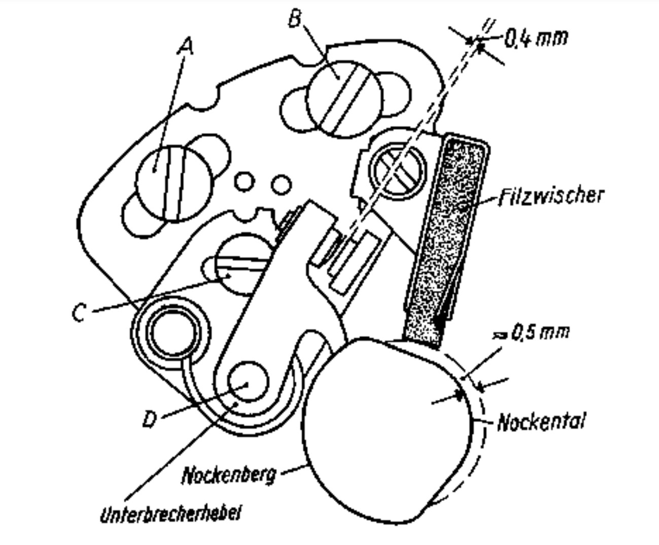
Figure 22. Adjusting the breaker and lubricating the breaker lever
The condition of the collector and brushes, as well as the tension of the brush springs are checked. The plus (+) brush wears faster than the minus (-) brush. The smallest height of the brushes may be 11 mm. After this height is reached, the brush should be replaced if possible. The grinding in of a new coal is best carried out by a specialist. Excessively worn brushes can completely destroy the alternator. In addition, the condition of the interrupter (tension of the interrupter spring, condition of the lever bearing, condition of the interrupter cam) is checked.

Figure 23. Regulator switch and intake silencer
a. fuse box with spare fuse
b. regulator switch
c. intake silencer
The ignition setting, which must be 4 mm before TDC (top dead center of the piston), is also checked on this occasion, because this setting changes during operation due to wear on the interrupter.
5.13. Battery care
The battery is very important for the proper functioning of the ignition and lighting system. The availability and reliability of the engine depends to a large extent on the condition of the battery. It therefore requires regular maintenance.
In the first few weeks of operation, the battery should be recharged twice from an external power source, because a new battery only gradually reaches its full storage capacity. In continuous operation, refilling from an external power source is normally not necessary. On the other hand, it is necessary to check the acid level in the battery every 2 months (or every 2000 km) and to top up the evaporated battery charge by pouring distilled water until the acid in each cell is about 10 mm above the plates. The battery connections must always be kept clean and checked for good contact and lubricated with terminal and contact grease after each cleaning. Twice a year - or about every 5000 km - have the acid density checked at a battery care station or by the IKA electrical service, if necessary add acid and recharge the battery.
5.14. Spark plugs - care
The spark plug changes during operation as a result of the high mechanical and thermal stresses to which it is exposed. It ages and regular maintenance of the spark plugs and monitoring of progressive aging is necessary to keep the engine reliable and safe to operate.
First of all, it is important that the inside of the plug is clean. Therefore, the spark plug must be unscrewed every 1000 km and cleaned with a wire brush (do not use a brass brush, burn out, or use so-called candle cleaners!). The correct electrode spacing is also important. It is 0.6 mm for Insulator spark plugs. Since this distance increases due to the electrode burn-off during operation, the side electrode must be re-bent until the correct dimension is restored, which can be checked by inserting a 0.6 mm thick feeler gauge or three postcards placed one on top of the other.

Picture 24. Candle control
The appearance of the inner parts of the spark plug, the so-called spark plug face, allows conclusions to be drawn about the combustion in the engine and thus makes it possible to identify and eliminate combustion faults and the errors that cause them in good time.
When screwing in the spark plug, which must be tightened sufficiently but not too tightly, do not forget to put the sealing ring underneath. The candles should be tightened often as they loosen over time.
After about 10,000 km, the spark plug has aged so much, even with the most careful care, that it can no longer withstand the stresses that occur in the engine. In order to avoid possible damage to the engine as a result, the spark plug must be replaced with a new one after around 10,000 km.
The correct spark plug must have a heat range of 240.
Under no circumstances should spark plugs with a lower heat range be used, as this could damage the engine. Plugs with a higher calorific value are unnecessary and only lead to operational difficulties.
5.15. Spark plug - assessment
Normal Appearance:
If the engine, carburettor and ignition setting as well as the fuel and lubricants used are in order, then the face of the plug will show an even rusty to fawn-brown insulating base after a longer period of operation. Depending on the operating time, the steel housing has a small amount of oil carbon or a thin, dry layer of soot. The electrode has a healthy, gray appearance.
Sooty spark plug:
The insulator base, electrode and housing are covered with a velvety, dry layer of soot.
Cause:
a. Plug glow value too high.
b. Unsuitable fuel.
c. Mechanical faults in the carburettor that lead to an enrichment of the fuel mixture (defective float needle, defective float).
d. Mechanical faults in the ignition system (dirty or stuck breaker lever, incorrect contact spacing, defective capacitor or ignition coil, ignition cable breaking through to ground).
e. Dirty air filter.
Oily spark plug (the insulator base, housing and electrode are coated with a damp, glossy black layer of oil).
Cause:
a. Plug temperature value too high.
b. Broken piston rings.
c. Worn piston or cylinder.
d. Clogged exhaust system.
e. Too much oil in the fuel mixture.
f. Carburettor setting too rich.
g. Malfunctions in the ignition system.
Overheated spark plug:
When the spark plug overheats, the insulator base is initially light-colored and covered with metallic beads. After a long period of operation, the insulator foot shows a grey-brown, partly steel-blue tinted, crusty and burned-on coating. The electrodes are pitted and badly burned off. The steel case shows tarnish colors due to overheating.
Cause:
a. Plug temperature level too low.
b. Carburettor setting too low.
c. Restricted fuel supply (fuel filter, fuel line clogged, carburettor dirty).
d. Ignition timing too early.
e. Leaking spark plug seat (i.e., forgot the sealing ring).
f. Carburettor mechanical faults resulting in poor fuel/air mixture (fuel level in float bowl too low, loose carburettor sloping, loose mixing chamber connection nut).
In any case, the gap between the spark plug electrodes must be checked.
5.16. Bulbs - Replace
The following bulbs are installed:
High beam, low beam A 6 V 45/40 W
Parking light H 6 V 1.5 W
Taillight, license plate light L 6 V 5 W
Brake light K 6V 18W
Flashing light K 6 V 18 W
Speedometer light J 6 V 1.2 W
Idle and fan control J 6 V 1.2 W
Charge Control J 6V 1.2W
After unscrewing the headlight cover ring you get to the headlight insert and the speedometer. After unscrewing the cap on the brake light license plate light you can access the bulbs of this light.
5.17. Headlight adjustment
The correct setting of the headlight is carried out by the manufacturer. It can be checked as follows:
a. The scooter must be set up vertically 10 m in front of the wall so that the longitudinal axis of the vehicle points to the vertical line on the wall. The dimension center headlight height is to be taken from the unloaded vehicle.
b. Load the scooter with 2 people.
c. With low beam, the upper horizontal part of the cut-off line must now be at least 10 cm below the specified center of the headlight. In addition, the bend in the light-dark boundary must lie on the drawn vertical line (a deviation of 20 cm to the right is allowed). Recognizing the kink is made easier if you temporarily cover the left side of the headlight. i.e., If there are discrepancies during this check, the headlight can be readjusted by removing the panel located under the headlight housing (nuts in the box). (If necessary, disconnect the horn). After loosening the hexagon screw on the housing under the headlight can be adjusted.

Figure 25. Adjusting the headlight
Headlight adjustment must be done very carefully and accurately. We therefore recommend that you visit an IKA specialist workshop for this purpose.
5.18. Fairing - paint care
The paint manufacturer recommends the following for cleaning and caring for the paintwork:
a. For wet washing: Globo car shampoo.
b. For polishing: Globo Lackbalsam or Globo Polish.
c. Procurement of spare parts - technical service
All spare parts for the "Troll 1" scooter can only be obtained by our customers from authorized workshops or specialist retail shops. This applies both to the parts we manufacture ourselves and to the parts we have supplied. The tires can only be obtained from specialist retail shops. It is therefore pointless to direct any spare parts orders to the manufacturer's works.
We have enough authorized workshops in the GDR that take over the technical monitoring of our vehicles during the warranty period and are available in the event of damage. For inquiries of a technical nature to the factory, please always state the engine and chassis number, the registration date and the mileage.
The chassis number is on the left side of the frame next to the traverse to which the fuel tank is attached, the engine number is on the left side of the engine housing at the front.
The type plate is attached to the right side of the frame, below the fuel tank.
Finally, our scooter customers should be told that the "Troll 1" scooter is subject to constant further development. It can therefore happen that individual details in the operating instructions are already outdated.
Copy of this manual came from ostmotorrad.de
German copy of the manual: https://dkwautounionproject.blogspot.com/2020/07/1964-iwl-troll-owners-manual.html
No comments:
Post a Comment