
Access to the Dynastart system as well as all work on the freewheel, chain, clutch and main transmission shaft are possible without removing the engine after loosening the engine side compartment panels and removing the front wheels. Special tools are required to pull off and hold the bell armature of the freewheel on the crankshaft and to release the clutch.
Checking Compression
When the throttle valve is fully open and the starter is cranked, compression must be between 5.3 and 5.8 atmospheres.
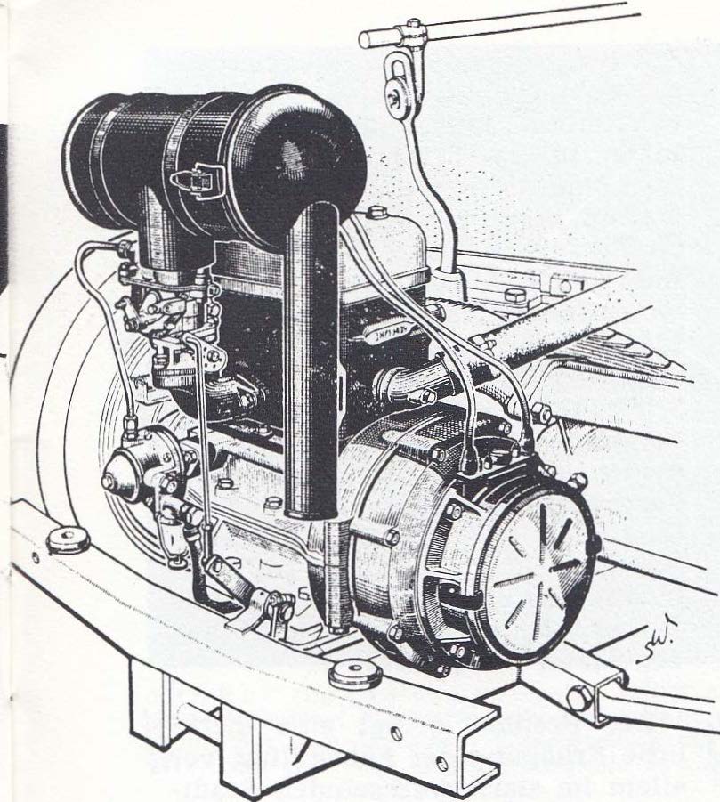
The Motor
 <
<
To remove the motor and gearbox unit one must first withdraw the drive shafts from the drive hubs by loosening the upper spring bolts and folding down the swivel bearings until the drive shaft can be extracted from the hub. The electrical connections, fuel line, accelerator lever (to carburetor), odometer cable, clutch cable, and freewheel cable must all be disconnected. The exhaust to front silencer must be unbolted. The gear shift must be disconnected and the gear lever pushed back through the radiator. The engine is mounted to the chassis via four bolts, two at the front of the engine and two at the rear of the drive hubs, under the radiator mounting frame. After these bolts are removed, the motor and gearbox unit is removed upwards after the radiator mask has been removed. Using an engine hoist, loop the wire rope around the cylinder block in such a way that the unit is tilted backwards against the radiator when it is lifted. It is also advisable to remove the hood by unscrewing the hinges, marking the original position so that it fits again during assembly.
Dismantling the engine
Block the transmission before dismantling the motor. When removing the chain drive, check the chain passage and chain track for wear. Note the regulating washers behind the clutch support ring, the latter are used to re-tension the chain. The thickness of the paper seals between the motor and gearbox housing, the total thickness of these seals must not exceed 2 mm.
The main and connecting rod bearings cannot be reworked in the workshop. Complete replacement crankshafts with all bearings are available in exchange. When installing a new shaft, it is essential to ensure that the center bearing bore in the housing is 0.01 to 0.02 mm smaller in diameter than the outer diameter of the center bearing ring on the crankshaft. It is advisable to measure the center bearing diameter with a micrometer and, after the housing halves have been turned off using the DKW facing tool, machine the housing bores with the DKW crankshaft bearing tool to the specified position. The centering collars of the flange bearings should have a clearance of 0.01-0.05 mm in the housing bores. Their diameter is therefore kept correspondingly smaller than the center bearing diameter, so that all three housing bores can be rubbed with the dimensions of the center bearing in one go. The planing of the housing halves has to be done in such a way that the surfaces are metallically sealed, rubbing may only take place on the screwed housing, whereby the stud bolts must be tightened to 4.5 mkg, as well as after inserting the shaft. After rubbing, the bearing surfaces of the lateral bearing flanges must be turned at right angles to the crankshaft center line, and the centering rim 220 (/) must be readjusted to accommodate the Dynastart machine.
The work described assumes that the necessary tools and devices are available and that the measurements are carried out properly. As these prerequisites are often not met, the factory not only keeps bare exchange shafts in stock at the spare parts depots, but also processed exchange housings with built-in shafts. The cylinders must be ground out if they have run out by more than 0.15 mm. It is advisable to only use original piston rings. Bolt identification by means of color to match the piston identification (color).
The right and left piston installation directions are marked. To install the piston pin, the piston must first be warmed to 85 ° C. The cylinder block is to be put on with the aid of piston ring tension bands. The paper seal on the cylinder base is 0.5 mm thick. The compression volume in the cylinder head for a compression ratio of 1: 6.75 is 60 ccm.

Fuel system
The inspection of this system essentially extends to checking the tightness of all connections, possibly measuring the pump pressure and occasionally cleaning the filter and carburettor. Idle speed may only be adjusted when the engine has warmed up. The starter carburettor is to be checked for complete shutdown when the control cable is released. No other nozzle models or sizes should be installed than those specified in the setting table.
In the cold season, the intake line must be inserted into the preheating hood on the exhaust manifold.
Ignition adjustment
1. Check spark plug and adjust the electrode gap as necessary.
2. Set the contact spacing on both breakers at the highest cam position.
3. Bring the right piston to 4.5 mm in front of above top dead centre (TDC). To do this, use the DKW setting gauge, which holds the OT automatically and by continuing to turn in the operating direction of rotation (clockwise on the Dynastart) to align the marking line on the indicator bolt with the 4.5 mm marking on the OT slide. Care! With new engines take great care not to damage the cam holder screw on the crankshaft. There is a risk of tearing it off.
If the engine is difficult to turn, rotate the left wheel hub in the direction of travel with 3rd gear engaged. Connect the test lamp between the right-hand breaker or the right-hand capacitor and ground and use a special key to fully eject the flyweights by turning the cam in the operating direction. Do not forget to switch on the ignition if the lamp does not light up. Loosen the interrupter base plate and move the interrupter to the left or right until the control lamp lights up when the centrifugal weights are fully ejected.
Re-tighten the screws and reconnect the lamp to the left breaker. Now bring the left piston to 4.5 mm in front of the upper TP and eject the flyweights. If the ignition timing on the 2nd cylinder is not correct, loosen the fastening screws of the 2nd plate on the base plate and adjust to the left or right until the control lamp lights up when the flyweights are completely ejected. All screw connections must be tightened well.
Please note, the breaker is no longer lubricated with warmed bearing grease or oils from the felt above the cam, as it used to be, but by filling the angle on the fibre blocks of the interrupter lever with special grease or roller bearing grease.
Transmission
The directly shifted three-speed gearbox is strong and simple in structure. The chain slack should be taken into account when dismantling. It is advisable to also indicate the direction in which the chain is running and ensure it is put back on exactly the same way. Seals up to a total thickness of 2 mm may be placed between the engine and the gearbox housing, otherwise the screw holes in the clutch cover will no longer fit. When replacing the bronze bushings for the countershaft, it is essential to ensure that it retains an axial play of approx. 0.1 to 0.2 mm. The running ring in the coupling sprocket should have an installation clearance of 0.08 to 0.1 mm. Note the oil hole position. Insert clutch springs (must all be the same height) into recessed seats, don't forget to check the chain track. To do this, place a ruler on the edge of the housing and measure the tooth flanks with a depth gauge after the coupling sprocket and drive sprocket. The coupling sprocket must protrude 0.3 to 0.4 mm from the drive sprocket. If necessary, compensate with washers behind the clutch support on the main gear shaft.
Special tools are required to dismantle and reassemble the rubber joints. - The inner drivers are conveniently slightly ground onto the cone. When removing the inner driver, a special impression device must be used, which is also required for dismantling the gearbox. It is also important to note the correct position of the shift linkage. If this is still done via the loop and roll, the setting must be made so that, regardless of which gear is switched on, there is still 3 mm of space between the end of the loop and the roll and the loop does not jam in the roll. In the newer version, it is operated via a fabric plate. The guides of the shift rod are adjustable, the guide rings are not lubricated.
Front axle
Changes in camber can only occur when moving off and the like. Corrections can only be made by adjustment on the frame or front spring. The control of the steering geometry (camber, caster etc.) is to be carried out with a special measuring device, whereby the regulations for front drive vehicles (use of turntables and brakes of the front wheels during the measurement process) must be observed.
Rear axle
The rear axle must be at exactly right angles to the longitudinal axis of the car. Misalignment can be corrected by adjusting the trailing arm. After adjusting the rear axle, check the position of the front spring or the front wishbones.

To adjust the brakes, jack up the vehicle, refill the brake fluid reservoir above the main brake cylinder (only use ATE Blue). In later models the fluid reservoir is accessible through a cover in the front floor panel. Brake adjustment screws are on the rear of the brake flange plate, 2 screws each - next to each other at the rear, opposite one at the front - recognizable by the claw springs underneath; Turn it until the wheel is firm, then back it evenly until the wheel just frees itself.
Danger! Welding work on the frame may only be carried out electrically.
Steering
Readjustment of the axial play of the steering wheel from the front is performed by means of an adjusting screw secured by a counter nut. The ability to adjust the steering damping is by means of a large slotted screw at the front (secured by a split pin). Below the screw, a spring presses onto the rack via a synthetic resin plug. Re-adjustment of radial pinion play is by adjusting and re-pinning the eccentric bearing bush. This can be accessed from the outside after releasing the clamping device on the special segment.
Electrical system and measuring devices

The maintenance and testing of the Dynastar system primarily includes measuring and possibly correcting the regulator open circuit voltage of 7.8 volts (plus - minus 0.1 volts). Here loosen cable 51 at the controller terminal and connect it to the output terminal, or better still to terminal 6. Measure the alternator voltage against the ground with a voltmeter at medium speed. If there are deviations from the nominal value, adjust the spring tension and thus the regulator tension by carefully bending the branch support bracket. Then, by switching on an ammeter between terminal 51 and cable 51 after switching off the ignition, determine the reverse current when the alternator coasts down. This should be 8-10 amperes. If necessary, the voltage can be brought to the prescribed value by carefully pushing the support bracket for the reverse current switch. After a running time of 15,000 to 18,000 km, the coils usually have to be replaced, which is possible after the pole iron has been removed.
The original publication in German - https://dkwautounionproject.blogspot.com/2020/12/dkw-f89p-and-f91-repair-instructions.html
Translation of the F91 repair instructions - https://dkwautounionproject.blogspot.com/2020/12/english-translation-of-austrian-dkw-f91.html
DKW F89P Meisterklasse owners manual - https://dkwautounionproject.blogspot.com/2018/02/dkw-f89p-new-meisterklasse-english.html
No comments:
Post a Comment